From Planning to Flush, Installation Made Simple
Installation of the Lift Assure System
Please read all of the following instructions before beginning installation.
-
Check to make sure the toilet functions properly before making any construction changes to the property.
-
Important: DO NOT flush anything other than organic human waste and toilet tissue.
-
DO NOT allow the unit to freeze.
-
Make sure any pipes exposed to freezing temperatures are insulated.
-
Check plumbing fixtures attached to the pump for leaks.
-
DO NOT use during a power failure, the pump will not operate causing the unit to overflow.
-
DO NOT use one-way air admittance valves. Macerating pumps needs two-way air movement.
-
The pump must be connected to a properly grounded GFCI- ground fault circuit interrupted receptacle on a dedicated 15 AMP circuit.
-
Always disconnect the power source before servicing or handling the pump.
-
DO NOT use an extension cord with unit.
-
Refrain from making any modifications to, or remove the ground pin from, the pump's power supply cord plug.
Recommended Materials
-
PVC/ABS Primer and Cement
-
1-1/4", 1-1/2" Rigid (Schedule 40) Pipe Fittings, as Needed
-
3" Pipe Extension and 3" Coupler (Depends on Installation)
-
Tee-wye Sewer Connection
-
Ball Valves Sized to Inlet and Discharge Pipe Sizes
-
2" Sewage Pump Check Valve (Depending on Installation)
-
For Optimal Performance, Use Long Sweep 90° Angles.
Required Tools
-
Pipe Saw
-
Philips Screw Driver
-
Flathead Screw Driver
-
5/16" Socket Wrench
-
Hammer
-
Level
-
Tape Measure
-
Drill
-
1/2" Masonry Drill Bit (Concrete Floors)
-
1/4" Drill Bit (Wood Floors)
Parts Included & Technical Specifications
-
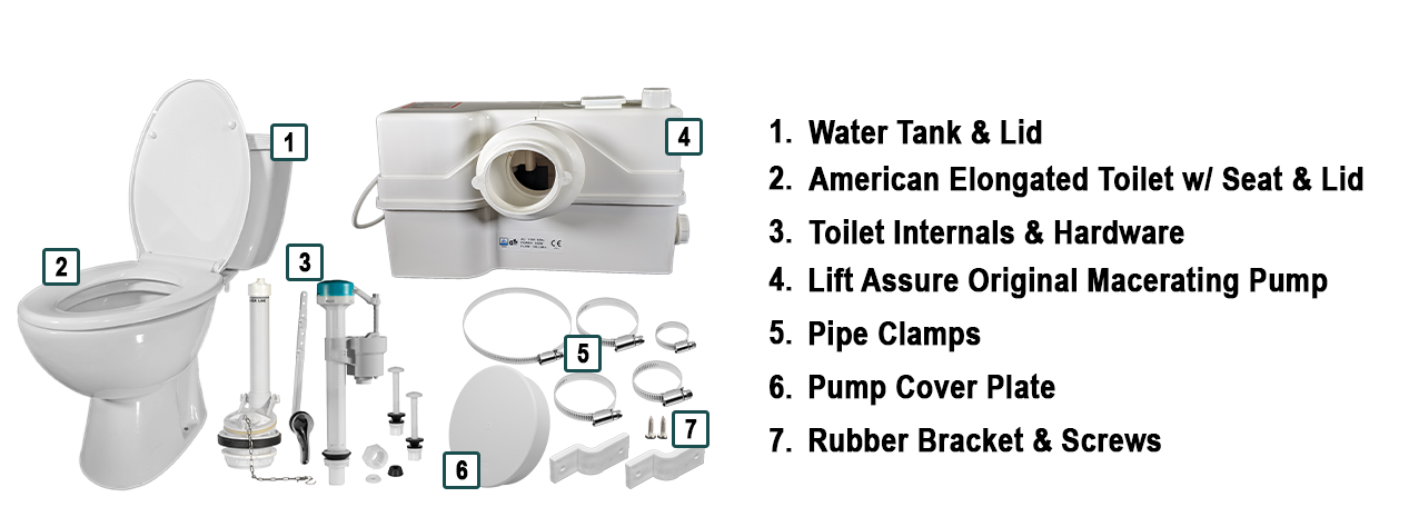
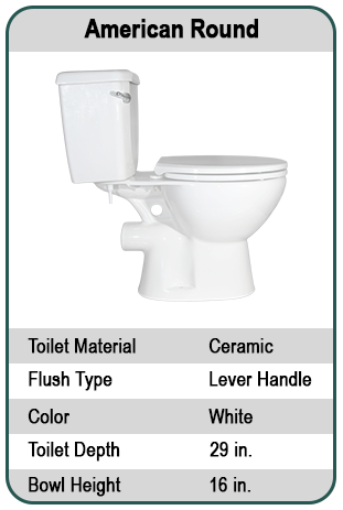
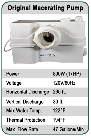
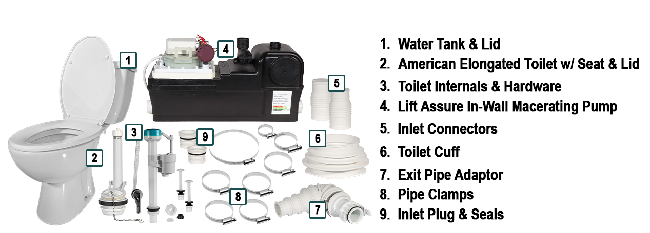
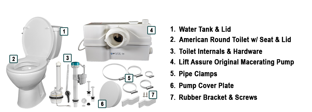
LA-Elongated + Original Pump Kit
-
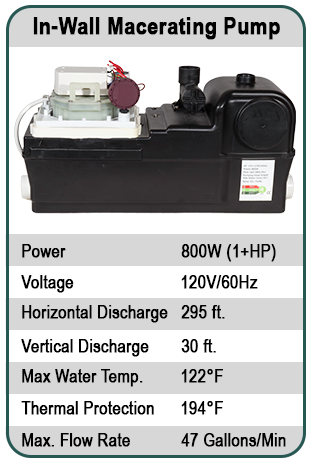
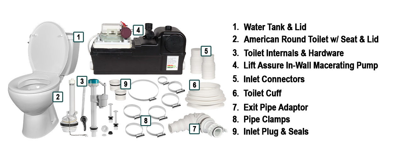
LA-Elongated + In-Wall Pump Kit
-
LA-Round + Original Pump Kit
-
LA-Round + In-Wall Pump Kit
Concrete Floor Installation:
Using Anchors:
Drill 2 holes using a 1/2" masonry drill bit; then insert the provided screws.
Wood Floor Installation:
Using Anchors:
Drill 2 pilot holes using a 1/4" drill bit.
Check the following before starting installation:
-
Floor site should be finished and level.
-
Check for clearance of doors and cabinets as well as any shower enclosure.
-
Ensure that all plumbing and electrical fixtures do not interfere with placement of bathroom fixtures.
-
Rough plumbing and electrical are completed to code.
-
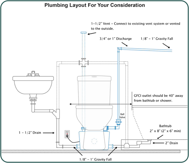
Placement of the electrical outlet must also meet local code. It is recommended to leave a 40" distance from bathtub/shower and within 6' of the pump.
-
Drill the floor holes for toilet placement. If installing on a concrete floor, install anchors, but DO NOT permanently secure fixtures until instructed.
IMPORTANT: Do not plug the macerator into an extension cord, for this is a safety hazard and can cause injury.
CAUTION: To permit proper drainage it is essential to elevate the shower/tub drain to minimum of 9" above the finished floor of the installed pump. If necessary, remember to adjust the height of the shower/tub drain upwards to allow proper grade for the plumbing connection to the pump. It is important to plan accordingly.
Part 1: Attaching Connections
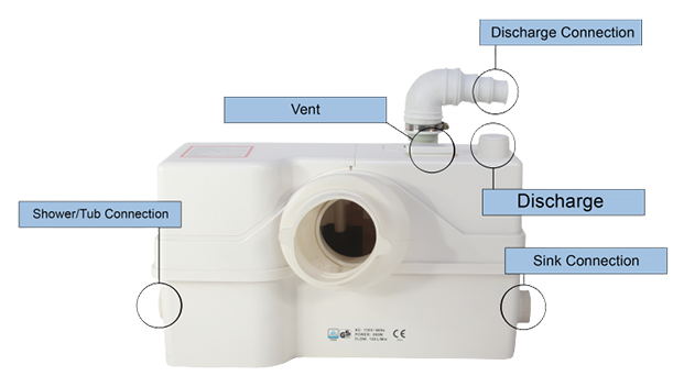
Vent Line: The macerating unit must be vented. It has 2 inlets on the top of the cover: a 1 ½" cap & a hole of smaller diameter. The unit must be connected to a vent system according to the plumbing codes. Put the waste inlet (provided) on the cap & clamp it down. After, connect the vent pipe. All fixtures connected to the system must also be vented.
Shower/Tub/Sink: To connect to the side entries of the case, use the side connector. Secure with clamps. Plug the unused inlet with blanking plug after greasing the joint. Ensure when connecting a shower to the macerating unit that the underside of the shower tray is raised at least 9" from the floor.
Discharge: These macerating units have an elbow and a bushing. Simply cut off the appropriate portion of the bushing in order to fit it to the discharge pipe. Use ridged wall pipe, not flexible pipe or hose, as flexible pipe may distort over time. Use 3/4" or 1" discharge pipe. Install a "full-part" ball or gate valve & a union in the discharge pipe in order to facilitate the removal of the macerating unit. Place the union or hose connector followed by the valve of the lower portion of the discharge pipe. If you need the unit to pump both vertically & horizontally, remember that 3 ft. of vertical lift is equal to 30 ft. of horizontal run. Discharge pipe work can be made from 3/4" diameter Type M Copper, CPVC, or PVC. Use long turn bends, not elbows. The connection to the soil-stack or sewer pipe must be made with an approved wye fitting. If you are not comfortable with this procedure, have a plumbing contractor install for you.
Part 2: Connection to Bath/Shower/Sink
Before making any connections, make sure there is proper slope of all horizontal runs.
Bath and Shower Attachment:
1. For proper draining it is essential to elevate the shower/tub drain to a minimum of 9" above the finished floor of the installed pump. If applicable, adjust the height of the shower/tub drain upwards to allow proper grade for the plumbing connection to the pump.
2. If bathtub is connected, the 2" connection can be reduced to 1-1/2" with adequate slope into the pump.
3. Measure rigid pipe from 2" pump inlet to shower/bath drain.
4. Cut pipe to fit, then connect shower/tub to 2" inlet with proper slope.
Sink Attachment:
1. Measure rigid pipe from sink drain to 1-1/2" pump inlet.
2. Cut pipe to fit.
Vent to Vent Stack Attachment:
IMPORTANT: Do not use one-way air admittance valves (or cheater vents). Macerating pumps need two-way air movement. They must also be vented to the outdoors.
1. Measure rigid pipe from vent on pump to vent connection. Either to new or existing vent stack.
2. Connect rigid pipe to main vent stack of house or directly outdoors.
ischarge Line Attachment:
IMPORTANT: The pump discharge outlet has a built-in check valve. Do not install an additional check valve as this may cause the pump to malfunction.
1. Install 1-1/4" ball valve approximately 6" from pump discharge outlet.
2. Install 1-1/4" plumbing line to the home's main waste line. There must be at least 3 feet of run from the pump before connecting to the main waste line.
Part 3: Connecting Toilet and Pump
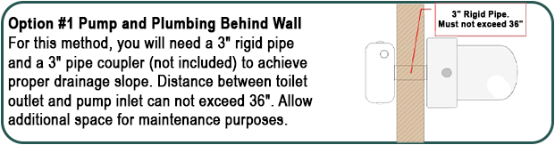
The following instructions apply for Option 1 shown above.
NOTE: ake sure the floor holes are drilled before you begin the following steps.
1. Drill a hole in the wall sized to accommodate pipe slope.
2. Position clamp onto the toilet outlet. *Hint: Apply soapy water to lubricate for easier clamp application; make sure you use non-petroleum based products only!
3. Install the pan gasket in place making sure it covers at least 1-1/2" of the toilet outlet.
4. Cut a 3" rigid pipe to fit; do not let it exceed 36".
5. Insert the pipe through the wall, connecting one end to the toilet outlet and the other to the macerator.
The pan gasket must cover at least 1-1/2" of the pipe. The side cover of the macerator must also cover at least 1-1/2" of the pipe.
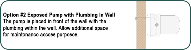
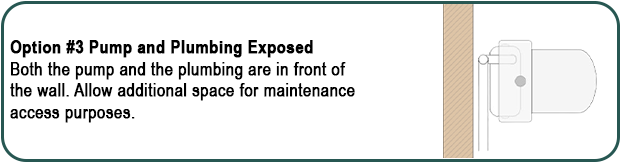
The following instructions apply for Option 2 and 3 shown above.
1. Position clamp onto the discharge outlet on the rear side of the toilet. If necessary, apply soapy water to lubricate the clamp for easy application.
2. Position the side cover of the macerator onto the toilet outlet and tighten, making sure it covers at least 1-1/2" of the outlet.
Part 4: Toilet Assembly
Note:
Assemble water tank as explained in the supplied instruction sheet, before proceeding with the following steps.
1. Check to make sure toilet is leveled before securing the toilet to the floor.
2. Install water tank in place. It is recommended to apply caulk around the base of the opening.
3. Secure the water tank with the provided nuts and bolts.
4. Verify that proper placement of the hose is established.
5. Install the seat cover bolts into the proper position, and secure by hand-tightening.
Part 5: Testing the System
1. Finish connecting all fittings and fixtures
2. Open the water supply valve to toilet and/or fixtures.
3. Check for leaks and correct as needed.
4. Plug the pump into wall outlet.
5. Flush toilet.
6. Double check for leaks; tighten and adjust clams and connections if necessary.
System Operation
What to Expect
This toilet operates on a different principle than a typical siphon toilet, resulting in a different sound and flush action. When activated, the pump pulses a few times.
Cleaning
Use only non-abrasive, non-petroleum products to clean the pump.
Prime the Pump
If pump initially runs for more than 10 seconds, prime the pump as follows:
a. Unplug cord from wall outlet.
b. Wait 15 seconds. Plug cord back into wall outlet.
c. Flush again. If pump runs more than 10 seconds, repeats steps a-c.
Winterization
If the Lift Assure system is exposed to freezing temperatures, please make sure that all fixtures, inlet, and discharge lines are winterized using non-toxic propylene glycol (RV Marine AntiFreeze). Use sufficient quantity of antifreeze to ensure all pipes are protected.
First, you must shut off the water supply. Flush toilet to empty the tank. Pour RV/Marine Antifreeze into toilet and all fixtures. Press manual switch to run antifreeze through system.
Clearing Debris from Pump
If the Lift Assure system is exposed to freezing temperatures, please make sure that all fixtures, inlet, and discharge lines are winterized using non-toxic propylene glycol (RV Marine AntiFreeze). Use sufficient quantity of antifreeze to ensure all pipes are protected.
While the Lift Assure does not need any maintenance under normal conditions, it is okay to clean out the macerating unit once a year. DO NOT use bleach. The macerating unit starts automatically once the toilet is flushed or the other bathroom appliance discharge and cease operation once the contents have finished pumping.


 0
0